
Page 86 - Hydrocarbon Exploration and Production Second Edition
P. 86
Drilling Engineering 73
Surface
Conductor/
stovepipe
Surface
casing
Intermediate
casing
Production
casing
Production
liner
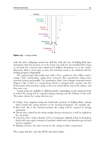
Figure 4.24 Casing scheme.
with the hole collapsing around the drill bit, with the loss of drilling fluid into
formations with low pressure or in the worst case with the uncontrolled flow of gas
or oil from the reservoir into unprotected shallow formations or to the surface
(blowout). Hence, from time to time, the borehole needs to be stabilised and the
drilling progress safeguarded.
5
The casing design will usually start with a 23 in. conductor, then 18 in. surface
8
3
5
casing, 13 in. intermediate casing above reservoir, 9 in. production casing across
8 8
reservoir section and possibly 7 in. production ‘liner’ over a deeper reservoir section
(Figure 4.24). A liner is a casing string which is clamped with a packer into the
bottom part of the previous casing; it does not extend all the way to the surface, and
thus saves cost.
Casing joints are available in different grades, depending on the expected loads
to which the string will be exposed during running, and the lifetime of the well.
The main criteria for casing selection are
Collapse load: originates from the hydrostatic pressure of drilling fluid, cement
slurry outside the casing and later on by ‘moving formations’, for example salt
Burst load: this is the internal pressure the casing will be exposed to during
operations
Tension load: caused by the string weight during running in; it will be highest at
the top joints
Corrosion service: carbon dioxide (CO 2 ) or hydrogen sulphide (H 2 S) in formation
fluids will cause rapid corrosion of standard carbon steel and therefore special steel
may be required
Buckling resistance: the load exerted on the casing if under compression.
The casing will also carry the BOPs described earlier.