
Page 107 - Improving Machinery Reliability
P. 107
Vendor Selection und Bid Conditioning 79
____
.
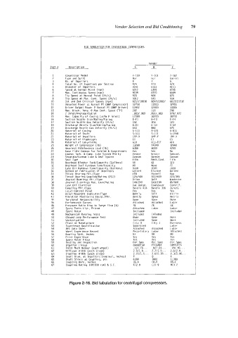
BID TABULATION FOR CENTRIFUGAL COMPRESSORS
___
Vendor
Item II
__ Description - - -
C
A
8
1 Compressor Model x - 100 Y-101 7-102
f Type and Split Hor Hor Barrel
3 NO. of Impellers 8 7 8
4 Total No. of Impellers per Section 414 hl 3 414
5 Diameter of Impellers ;% O(B1 O(C)
6 Speed at Normal Point (rpm) 8305 8180
7 Max. Continuous Speed (rpm) 9039 8720 8589
8 Tip Speed at Normal Point (ftls) 920 900 870
9 Tip Speed at Max. Cant. Speed (ftls) 1012 945 914
10 1st and 2nd Critical Speeds (rpm) 6217118010 6847119807 6617121530
11 Absorbed Power at Normal PT (BHP Cornpressor) 12750 12813 12955
12 Oriver Output Power P Norniai Pl (BHP Oriver) 12802 12900 13005
13 Max. Disch. Temp. @ Max Cant. Speed (‘F) 292 318 798
14 Z InletIAveragelOutlet ,9831 ,969 9911.983 9791.972
15 Max. Capacity of Casing (acfm (a inlet) 17000 16200 18250
16 Suction Nozzle SizeIRatinglFacinq 0-F1 043 0-F4
17 Suction Nozzle Gas Velocity (ftls) 102 108 123
18 Oischarge Nozzle SizelRatinglFacing 0-GI 0-G3 0-G4
19 Discharge Nozzle Gas Velocity (ftls) 650 680 670
20 Material of Casing A-111 A-I21 A-811
21 Material of Shaft 5-111 5-111 5-1550
22 Material of Impellers IMP-X IMP-Y IMP-X
23 Material of Oiaphragms CI Cl cs
24 Material of Labyrinths ALU ALU-TEF ALU
25 Weight of Compressor (Ib) 13280 14000 12860
26 Heaviest Maintenance Load (Ib) 6380 6000 4280
27 Base Plate Comnon for Turbine & Compressors Yes Yes NO
28 Common Turb. & Camp. Lube System Mfd by Vendor Vendor Subcont
29 SeparateICormion Lube & Seal Systein Conmon Comnon Cormon
30 Seal Type Film Mec h .Con t . Film
31 Overhead Bladder TanklCapacity (Gal Ions) 58 62 123
32 Overhead Seal Rundown TankICapacity 88 None 72
33 Lube Oil Rundown TanklCapacity (Gallons) 1000 2000 zoo0
34 Method of Fabrication of Impellers Welded Riveted Welded
35 Thrust Bearing Mfr.1Type KTB Michell Own
36 Thrust Hearing LoadinglRating (PSI) 1251500 1821600 2201300
37 Journal Bearings Mfr.1Type Orion Self Waukesha
38 Journal B earings Max. LoadIRating 1401200 1401180 851500
39 Lube Oil Clarifier Vac .Dehyd. Coalescer Centrif.
40 Coupling Mfr.IType Bendix 416 Bendix 316 2urnIG
41 Local Control Panel Yes Yes Yes
42 Axial Movement IndicatorIType Bently Seif Airfix
43 Vibration Moni taring Equip ./Mfr . Bently Oynac Metrix
44 Torsional Respansibiljty None None None
45 Performance Curves Attached Attached Later
46 Pressure Ratio Rise to Surge Flow (X) 7% 7% 3%
47 Spare Parts List, Priced Attached Later Later
48 Spare Rotor Included 1 nc 1 uded
49 Mechanical Running Tests Inc 1 uded lnluded
50 Closed Loop Performance Test None None None
51 Winteri zat ion Included None None
52 Place of Manufacture City H City J Overseas
53 Experience Qual if ication Submitted Later
54 API Data Sheet Attached Attached Later
55 Wheel Experience Record Proprietary Later Attached
56 Bearing Span, inches 83 90 80
57 Prior Experience Yes Yes Yes
58 Spare Rotor Fitup Yes Yes Yes
59 Testing and Inspection Per Spec Per Spec Per Spec
60 Impeller Lineup CAABCFGH FFCDAEA GWPJFSS
61 Inlet Mach Number (each wheel) .72/ .?E.. . -821.91. . . .7a1.81...
62 Oiffuser Width (each stage) 2.511.8.. . 2.711.9 2.612.0 ...
63 Impeller Width (each stage) 2,2511.5 ... 2.612.38.. 2.311.86..
64 Shaft Oiam. at Impellers (nominal, inches) P n R
65 Shaft Stress at Coupling, psi 6380 is80 11380
66 Coupling Hare, inches CB-A CH-B CB-C
67 Couplinq Ratinq (HPIIOO rpm) & S.F. K12.8 Ll2.9 M13.2
Figure 2-16. Bid tabulation for centrifugal compressors.