
Page 224 - Improving Machinery Reliability
P. 224
Machinery Reliability Audits arid Reviews 195
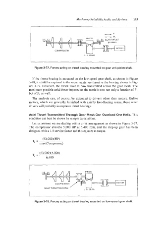
Figure 3-77. Forces acting on thrust bearing mounted on gear unit pinion shaft.
If the thrust bearing is mounted on the low-speed gear shaft, as shown in Figure
3-78, it could be exposed to the same rnaxkadin thrust as the bearing shown in Fig-
ure 3-77. However, the thrust force is now transmitted across the gear mesh. The
maximum possible axial force imposed on the mesh is now not only a function of FT
but of F, as well.
The analysis can, of course, be extended to drivers other than motors. Unlike
motors, which are generally furnished with axially free-floating rotors, these other
drivers will probably incorporate thrust bearings.
Axial Thrust Transmitted Through Gear Mesh Can Overload One Helix. This
condition can best be shown by sample calculations.
Let us assume we are dealing with a drive arrangement as shown in Figure 3-77.
The compressor absorbs 5,000 HP at 6,400 rpm, and the step-up gear has been
designed with a 1.5 service factor and this equates to torque.
(63,000)( HP)
T, =
rpm (Compressor)
(63,000)(5,000)
T, =
6,400
COMPRESSOR
’
GEAR THRUST BEARING L S GEAR
GEAR THRUST BEARING
L S GEAR
Figure 3-78. Forces acting on thrust bearing mounted on low-speed gear shaft.