
Page 225 - Improving Machinery Reliability
P. 225
196 Improving Machinery Reliability
or 49,200 lb-in. Using a pinion pitch diameter of 12 in, the tangential driving load
would be
or 8,200 Ibs. This tangential driving load can be resolved into axial-thrust compo-
nents by multiplication with the tangent of the helix angle. For 9 = 30°, the axial
thrust per helix will equal (8,200/2) tan 30°, or 2,365 Ibs. In addition, it is readily
evident that the gear mesh can be exposed to an external force, FA. The magnitude of
FA is the lesser of the two values, F, or MA typically around 1,200 lbs for a 5,000 HP
induction motor turning at 1,780 rpm, and
Since the motor torque TLss is (63,000) (5,000)/1,780 = 177,000 Ib-in., and low-
speed coupling pitch diameters Dp~s are probably in the 10 in to 12 in range, F2 will
no doubt be significantly larger than MA. Accordingly, the magnetic centering force
of the motor constitutes the external force imposed on the gear mesh, i.e. it may cre-
ate an axial push or pull acting through coupling teeth that refuse to slide.
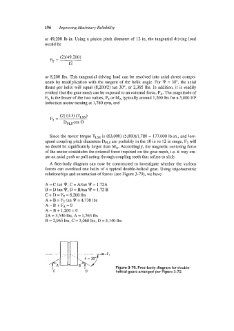
A free-body diagram can now be constructed to investigate whether the various
forces can overload one helix of a typical double-helical gear. Using trigonometric
relationships and summation of forces (see Figure 3-79), we have
C
A = C tan q, =Ahan v'= 1.72A
B =D tan 9, D = B/tan 9= 1.72 B
C + D = FT = 8,200 IbS
A + B = FT tan 9 = 4,730 lbs
A - B + FA = 0
A-B+ 1,200=0
2A = 3,530 lbs, A = 1,765 lbs
B = 2,965 lbs, C = 3,060 lbs, D = 5,140 lbs
* = 30"
Figure 3-79. Free-body diagram for double-
C D helical gears arranged per Figure 3-72.