
Page 349 - Improving Machinery Reliability
P. 349
Extending Motor Life in the Process Plant Environment 315
the frame as it passes through the stator slots and from short circuiting to adjacent
coils. Adjacent coils are connected to different phases and are at different potentials
at any given time. Very large motors have heavy, formed coil wires instead of
wound coils. These are individually wrapped with insulating material before inser-
tion into the stator slots.
After the coils, slot insulation and phase insulation are all in place, the entire stator
assembly is varnished to stabilize and adhere the windings to each other. The varnish
is not part of the insulation system. Its purpose is to prevent turn-to-turn movement
from induced magnetic force, and possible abrasion of the windings when the motor is
under load. On motors intended for use in extreme-moisture environments, the wind-
ings may be totally encapsulated in polyester resin to both stabilize and protect them.
Insulation Classification
Some insulation materials are better able to withstand heat, Le., have greater ther-
mal capacity, than others. And some motors, because of high watt losses and the rel-
ative limitations of their ventilation systems, will experience higher temperature
rises above ambient than others during operation. Classifications based on thermal
capacity have been established for insulation systems. Classifications, Table 6- 1,
define the maximum allowable temperature rise the system materials may withstand
without premature failure. In general, the cost of insulation materials and systems
increases in proportion to their thermal capacity.
Class A insulation systems for small and medium single-phase and three-phase
motors include materials that will deliver suitable life when the motor is operated up
to the limiting (maximum) Class A temperature of 105°C. Class B systems are
designed for a limiting temperature of 130°C; Class F for 155°C; Class H for 180°C.
Ambient Plus
The operating temperature of the motor insulation includes the ambient tempera-
ture plus any temperature rise during operation that the ventilation system is unable
to prevent.
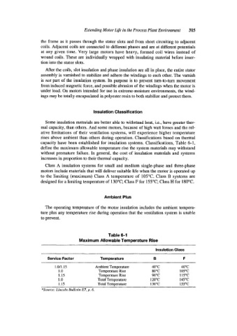
Table 6-1
Maximum Allowable Temperature Rise
Insulation Class
service Factor Temperature B F
1.0/1.15 Ambient Temperature 40°C 40°C
1 .0 Temperature Rise 80°C 105°C
1.15 Temperature Rise 90°C 115°C
I .0 Total Temperature 120°C 145°C
1.15 Total Temperature 130°C 155°C
*Source: Liricoln Bulletin E7, p. 6.