
Page 129 - Industrial Cutting of Textile Materials
P. 129
116 Industrial Cutting of Textile Materials
9.2 Automated cutting systems and their main parts
Automated cutting systems are used to process a wide variety of sheet and rolled
materials. Despite differences in the cutting tools and materials to be cut, the work
principles and main parts involved in automated cutting process are similar. These
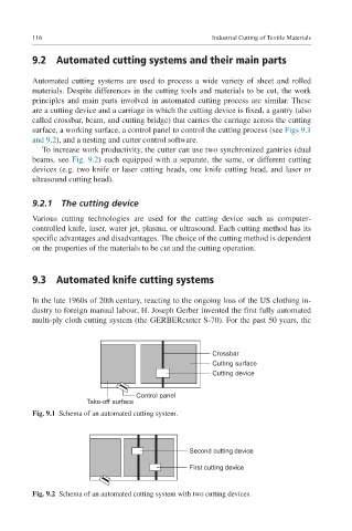
are a cutting device and a carriage in which the cutting device is fixed, a gantry (also
called crossbar, beam, and cutting bridge) that carries the carriage across the cutting
surface, a working surface, a control panel to control the cutting process (see Figs 9.1
and 9.2), and a nesting and cutter control software.
To increase work productivity, the cutter can use two synchronized gantries (dual
beams, see Fig. 9.2) each equipped with a separate, the same, or different cutting
devices (e.g. two knife or laser cutting heads, one knife cutting head, and laser or
ultrasound cutting head).
9.2.1 The cutting device
Various cutting technologies are used for the cutting device such as computer-
controlled knife, laser, water jet, plasma, or ultrasound. Each cutting method has its
specific advantages and disadvantages. The choice of the cutting method is dependent
on the properties of the materials to be cut and the cutting operation.
9.3 Automated knife cutting systems
In the late 1960s of 20th century, reacting to the ongoing loss of the US clothing in-
dustry to foreign manual labour, H. Joseph Gerber invented the first fully automated
multi-ply cloth cutting system (the GERBERcutter S-70). For the past 50 years, the
Crossbar
Cutting surface
Cutting device
Control panel
Take-off surface
Fig. 9.1 Schema of an automated cutting system.
Second cutting device
First cutting device
Fig. 9.2 Schema of an automated cutting system with two cutting devices.