
Page 236 - Industrial Power Engineering and Applications Handbook
P. 236
Transmission of load and suitability of bearings 8/215
No rotating mass can be balanced up to 0 micron, for load farther away from the shaft collar, it is recommended that the
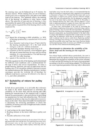
obvious reasons. While rotating they are out of balance, pulley be mounted on a separate jack shaft, supported on two pedestals
which gives rise to rotating forces and adds to the radial as illustrated in Figure 8.15. Provided that the motor shaft can be
load on the bearing. This indirectly affects the running made longer, to support such a pulley and have sufficient strength,
life of the bearing, in addition to other factors noted to take that load, one pedestal may also be adequate to support the
free end of the motor shaft as shown in Figure 8.16. The pulley is
above. The selection of type and size of bearing, is thus now mounted between the shaft collar and the pedestal. A jack
governed by the speed of the machine, the type and weight shaft or additional pedestal to support the motor shaft may also be
of loads and the required life of the bearing which can be necessary when the ratio of pulley diameters exceeds 6:l.
expressed by In some cases, reinforcement of the shaft by increasing the
shaft diameter, employing a better grade of steel and using a superior
grade of bearings, may also meet the load requirement. The bearing
106
Ll0 = - (g)' hours (8.4) bore, however, may pose a limitation in increasing the shaft diameter
60. N, beyond a certain point, say, beyond the diameter of the shaft collar.
If a larger shaft diameter is required either a larger frame size of the
where motor may be employed, which may be uneconomical, or a jack
L,, = Rated life of bearings at 90% reliability, i.e. 90% shaft or pedestal may be used as noted above. Replacing standard
of bearings produced by a manufacturer will exceed bearings with larger bore bearings to use a shaft of greater diameter
this life may not be possible in the same frame, due to pre-sized end shields
C = basic dynamic load rating in kg or N (provided by and bearing housings which, for motors up to 250 kW, are normally
the bearing manufacturer). It is the load which cast and have fixed dimensionshoulding patterns.
will give a life of I million revolutions
P = equivalent dynamic bearing load in kg or N Questionnaire to determine the suitability of the
p = exponent of the life equation, which depends upon motor shaft and the bearing for the required
the type of contact between the races and the rolling belt drive
elements. It is recommended as 3 for ball bearings
and 10/3 for roller bearings For critical loads and belt drives particularly, the user is
N, = speed of the machine in r.p.m. advised to seek the opinion of the motor manufacturer to
determine the mechanical suitability of the motor selected,
With this equation the life of the bearing can be determined its shaft and the DE bearing for the load to be transmitted,
for different load conditions and is predetermined for according to the drive system being adopted. The following
the type of drive and service requirements. To select a are some important parameters that may help to determine
proper bearing, therefore, the type of application and the
loading ratio (ClP) should be carefully selected to ensure
the required minimum life. Bearing manufacturers' product Pedestal bearing-, -
catalogues provide the working life of bearings for
different load factors and may be referred to for data on
C, C, and other parameters.
I Abearing
8.7 Suitability of rotors for pulley
drives se
me
In belt drives particularly, it is advisable that reference
be made to the motor manufacturer to determine the
suitability of the rotor shaft and the driving end (DE) Figure 8.15 Arrangement of a jack shaft
bearing for transmission of the required load. A typical
format of a questionnaire is also given below for providing
the manufacturer for load, belt and pulley data. The format 7
is suitable for all drives that may be subjected to excessive Motor
Shaft collar
forces on the shaft. These data will enable the manufacturer Pulley
to determine the following parameters to check the I
suitability of bearing and shaft strength and make suitable Long shaft
changes if warranted: 7
Pedestal
bearing
Load acting on the motor bearings
Bending moment at the motor shaft due to pulley and
load
Possible deflection of the shaft Base
frame
Note The shaft deflection should not be more than 1 1 % of the air
gap between the stator and the rotor. For loads that exert more force
and torsional stress on the motor shaft and bearings than is
permissible, due to the larger width of pulleys which may shift the Figure 8.16 Arrangement of a long shaft