
Page 57 - Industrial Power Engineering and Applications Handbook
P. 57
2/38 Industrial Power Engineering and Applications Handbook
made of these two cages, having a low effective resistance,
being in parallel. In such designs, therefore, the speed-
torque curve can be achieved to take any desired shape
by suitably choosing the resistances of the two cages,
the width of the slot opening and the depth of the inner
cage. The equivalent circuit diagram of a motor with a
single and a double cage rotor is illustrated in Figure 2.4
(a) and (b) respectively. To draw the speed-torque curve
for such a motor theoretically, consider the two cages
developing two different torques separately. The effective
torque will be the summation of these two, as shown in
Figure 2.5.
Notes
The inncr and outer cages are separated by a narrow slit to
facilitate linking of the main flux with the inner bars which are
quite deep.
HT motors are also manufactured with double cage rotors. They
are designed especially to match a particular load requirement
when the load characteristics are known, or as in NEMA class
C, or as the manufacturer’s own practice, when the starting
torque requirement exceeds 150% of the full-load torque (FLT).
The likely applications for a high starting torque may be induced-
draught fans, blowers, coal crushers, mill motor5 and coal
conveyor motors.
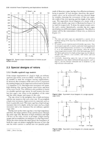
Generally. depending upon the type of load, different
Figure 2.3 Speed-torque characteristics of motors as per manufacturers may adopt to different design practices, such as
NEMA standard high T,, and low thermal withstand time or moderate T,, and
high thermal withstand time.
2.3 Special designs of rotors
2.3.1 Double squirrel cage motors
If the torque requirement of a load is high, an ordinary
squirrel cage motor, even on a DOL* switching, may not
be suitable to meet the stringent starting requirements.
If, however, the resistance of the rotor circuit is increased
the starting torque can be improved as discussed in Section
1.2 (equation (1.3)). But high rotor resistance will mean -
Ri
high running slip, causing greater rotor losses and heat s
in the rotor circuit. The solution to this problem is found
in a double squirrel cage motor. In such motors the rotor
has two cages, one closer to the periphery of the rotor
Figure 2.4(a) Equivalent circuit diagram of a single squirrel
and the other deeper and nearer to the core. cage motor
The one closer to the periphery has a high resistance
and the one nearer to the core a low one. To accomplish
a high rotor resistance, high-resistivity materials such as
brass is generally used. The inner cage has a high leakage
reactance due to its depth, while the outer one has a high
resistance and a low reactance like an ordinary squirrel
cage rotor.
During start-up the inner cage has a very high impedance
and thus, the larger portion of the current passes through
the outer cage only. Because of high resistance and high
12R loss in the rotor circuit, it develops a high starting
torque and accomplishes an analogue to a slip-ring motor.
When the rotor reaches the rated speed, the reactances of
both the cages are almost negligible because of low slip
and the rotor current is carried into two parallel paths
1st cage 2nd cage
Figure 2.4(b) Equivalent circuit diagram of a double squirrel
*DOL - Direct On-line cage motor