
Page 23 - Industrial Process Plant Construction Estimating and Man Hour Analysis
P. 23
xxxviii Introduction
The unit-quantity model is given by
X
MH t ¼ n i MH i Þ
ð
where
MH t ¼man-hours for equipment and piping field installation
n i ¼task takeoff quantity i, in dimensional units
MH i ¼unit equipment/piping man-hour associated with n i
i¼Task 1, 2, m from quantity takeoff associated w/ field equipment/piping
The n i quantity is the takeoff for the field scope of work.
MH i unit man-hours are determined from piping and major equipment man-
hour tables.
The unit man-hours were determined from historical data, and they
correspond to the labor productivity necessary to install piping and equipment
in an industrial construction facility.
The unit-quantity method allows a final cross-check of actual man-hours to
estimated man-hours.
Factor:
ðÞ
ð
MH t ¼ n i MH i Þ f u
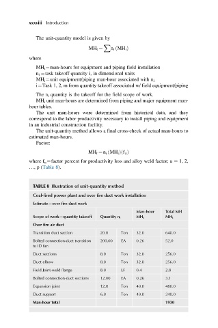
where f u ¼factor percent for productivity loss and alloy weld factor; u ¼ 1, 2,
…,p (Table 8).
TABLE 8 Illustration of unit-quantity method
Coal-fired power plant and over fire duct work installation
Estimate—over fire duct work
Man-hour Total MH
Scope of work—quantity takeoff Quantity n i MH i MH t
Over fire air duct
Transition duct section 20.0 Ton 32.0 640.0
Bolted connection-duct transition 200.00 EA 0.26 52.0
to ID fan
Duct sections 8.0 Ton 32.0 256.0
Duct elbow 8.0 Ton 32.0 256.0
Field Joint-weld flange 8.0 LF 0.4 2.8
Bolted connection-duct sections 12.00 EA 0.26 3.1
Expansion joint 12.0 Ton 40.0 480.0
Duct support 6.0 Ton 40.0 240.0
Man-hour total 1930