
Page 125 - Industrial Ventilation Design Guidebook
P. 125
4,2 STATE VALUES OF HUMID AIR; MOLLIER DIAGRAMS AND THEIR APPLICATIONS 87
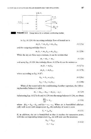
FIGURE 4.1 I Energy balance for an adiabatic conditioning chamber.
In Eq. (4.124) the incoming enthalpy flow of humid air is
and the outgoing enthalpy flow is
While the dry air flow stays constant, it can be written that
and using Eq. (4.126) the enthalpy flows (4.125a-b) can be written as
where according to Eq. (4.87)
When all the water fed to the conditioning chamber vaporizes, the follow-
ing humidity balance is valid:
Substituting Eqs. (4.127a-b) and (4.129) into the energy balance (4.124), we obtain
where &h k = k k2-b ki and AJC = x 2-x 1. When air is humidified adiabati-
cally with water with temperature 0 ad, the enthalpy of water is now
If, in addition, the air is humidified so that it reaches the saturation point,
with the corresponding temperature 0 ad, we will now use the notations