
Page 146 - Industrial Ventilation Design Guidebook
P. 146
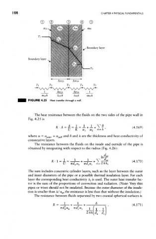
1 08                                                CHAPTER 4 PHYSICAL FUNDAMENTALS


                      FIGURE 4.25 Heat transfer through a wall.


                         The heat resistance between the fluids on the two sides of the pipe wall in
                      Fig. 4.25 is


                      where a = a conv + a rad, and 8 and A are the thickness and heat conductivity of
                      consecutive layers.
                         The resistance between the fluids on the inside and outside of the pipe is
                      obtained by integrating with respect to the radius (Fig. 4.26):


                      The sum includes concentric cylinder layers, such as the layer between the outer
                      and inner diameters of the pipe or a possible thermal insulation layer. For each
                      layer the corresponding heat conductivity Aj is used. The outer heat transfer fac-
                      tor is the sum of the proportions of convection and radiation. (Note: Very thin
                      pipes or wires should not be insulated. Because the outer diameter of the insula-
                      tion is smaller than A/a M, the resistance is less than that without the insulation.)
                         The resistance between fluids separated by two coaxial spherical surfaces is