
Page 149 - Industrial Wastewater Treatment, Recycling and Reuse
P. 149
Advanced Physico-chemical Methods of Treatment for Industrial Wastewaters 123
In the vortex diode, D represents the diode chamber, while H is the
chamber height. The diameters at different points at the inlet and outlet
are represented in the figure by the shaded regions and can be parameters
for specific design. As can be seen, the design can have many variations
in the size and shape of chamber and modifications that can alter the flow
pattern within the device. The flow through the device is complex, and
some studies using computational fluid dynamics have been carried out to
obtain insight into the flow pattern and its impact on the cavitation process
(Bashir et al., 2011; Kulkarni et al., 2008; Pandare and Ranade, 2013). How-
ever, as far as application of cavitation technology to wastewater is con-
cerned, the approach is largely empirical with preliminary experimental
studies required for obtaining useful data on the degradation of pollutants
and the optimization of process parameters, similarly to coagulation processes.
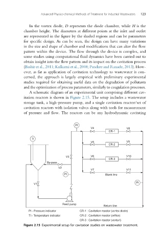
A schematic diagram of an experimental unit comprising different cav-
itation reactors is shown in Figure 2.15. The setup includes a wastewater
storage tank, a high-pressure pump, and a single cavitation reactor/set of
cavitation reactors with isolation valves along with tools for measurement
of pressure and flow. The reactors can be any hydrodynamic cavitating
PI
V4 V8
CR-1
TI
V5 V9
CR-2
V3 V6 V10
CR-3
By-pass
V2
V7 V11
PI Blank line
PI
V1
Feed pump
Return line
PI - Pressure indicator CR-1 : Cavitation reactor (vortex diode)
TI - Temperature indicator CR-2 : Cavitation reactor (orifice)
CR-3 : Cavitation reactor (venturi)
Figure 2.15 Experimental setup for cavitation studies on wastewater treatment.