
Page 172 - Industrial Wastewater Treatment, Recycling and Reuse
P. 172
146 Industrial Wastewater Treatment, Recycling, and Reuse
Quartz tube
T1
T6 T2
Sound waves Effluent in hexagonal
annular part in batch mode
T5 T3
T4
Ultrasound
transducers
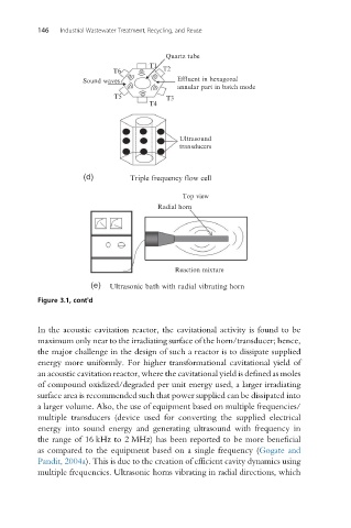
(d) Triple frequency flow cell
Top view
Radial horn
Reaction mixture
(e) Ultrasonic bath with radial vibrating horn
Figure 3.1, cont'd
In the acoustic cavitation reactor, the cavitational activity is found to be
maximum only near to the irradiating surface of the horn/transducer; hence,
the major challenge in the design of such a reactor is to dissipate supplied
energy more uniformly. For higher transformational cavitational yield of
an acoustic cavitation reactor, where the cavitational yield is defined as moles
of compound oxidized/degraded per unit energy used, a larger irradiating
surface area is recommended such that power supplied can be dissipated into
a larger volume. Also, the use of equipment based on multiple frequencies/
multiple transducers (device used for converting the supplied electrical
energy into sound energy and generating ultrasound with frequency in
the range of 16 kHz to 2 MHz) has been reported to be more beneficial
as compared to the equipment based on a single frequency (Gogate and
Pandit, 2004a). This is due to the creation of efficient cavity dynamics using
multiple frequencies. Ultrasonic horns vibrating in radial directions, which