
Page 179 - Industrial Wastewater Treatment, Recycling and Reuse
P. 179
Advanced Oxidation Technologies for Wastewater Treatment: An Overview 153
In HC, the cavitational yield (e.g., the amount of pollutant degraded/
mineralized per unit energy dissipated) depends on the intensity of cavity
collapse, which in turn depends on several parameters, such as number of
cavitational events, the maximum size of the cavity reached before its col-
lapse, and the surrounding pressure field. In HC, all these parameters depend
on the geometry of the cavitational device and the operating parameters.
Important parameters that decide degradation efficiency and the overall
cavitational yield are the following:
• Inlet pressure and the cavitation number
• Physicochemical properties of the liquid and the initial radius of the
nuclei
• Size and shape of the throat and divergent section (in the case of venturi)
• Percentage cross-sectional free area offered for the flow.
3.2.2.1 HC Reactor
Different HC setups with different types of cavitating device have been used
such as the single-hole orifice plate, the multiple-hole orifice plate, the cir-
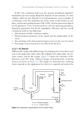
cular venturi, and the slit venturi. Figure 3.3 shows the schematic of the
laboratory-scale HC setup. Different designs of hydrodynamic cavitating
devices are shown in Figure 3.4. The design of a hydrodynamic cavitating
device depends on the application for which it is required and needs to be
Main
line
Cooling Bypass P 2
water out line
Cavitating device
P 1
Cooling Tank
water in V 2 V 3
V 1
Pump
, P – Pressure gauges
P 1 2
, V , V – Control valves
V 1 2 3
Figure 3.3 Schematic representation of HC reactor setup.