
Page 180 - Industrial Wastewater Treatment, Recycling and Reuse
P. 180
154 Industrial Wastewater Treatment, Recycling, and Reuse
first optimized in terms of the cavitational intensity required for the desired
application. A typical HC setup consists of a closed loop circuit, including a
feed tank, pump, pressure gauges, and valves. The bottom side of the feed
tank is connected to the suction side of the pump. The discharge line from
the pump is branched into two lines. The first line is for bypass and the
second line is described as main line which contains a cavitating device.
A bypass line is provided to control the flow through the main line contain-
ing the cavitation device. Control valves (V 1 , V 2 , and V 3 ) are provided at
appropriate places in the bypass line and before cavitating devices in main
line to control the flow through the cavitating device. Pressure gauges are
provided to measure the inlet pressure (P 1 ) and fully recovered downstream
pressure (P 2 ).
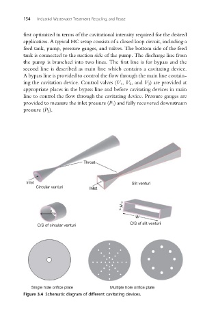
Throat
Inlet Slit venturi
Circular venturi Inlet
H
d o
W
C/S of slit venturi
C/S of circular venturi
Single hole orifice plate Multiple hole orifice plate
Figure 3.4 Schematic diagram of different cavitating devices.