
Page 274 - Industrial Wastewater Treatment, Recycling and Reuse
P. 274
248 Industrial Wastewater Treatment, Recycling, and Reuse
6.4 MFCs FOR HARVESTING BIOELECTRICITY FROM WASTE
REMEDIATION
The energy gain in microbes is driven by oxidizing an electron donor and
reducing an electron acceptor (Venkata Mohan, 2012; Venkata Mohan
et al., 2013a). Variation in the electron acceptor conditions facilitates in har-
vesting energy. As a part of microbial respiration, electrons move to an
exocellular medium towards the available electron acceptor, such as metals,
nutrients, minerals, and solid electrodes, in the absence of oxygen (Franks
and Nevin, 2010; Logan, 2008, 2010; Venkata Mohan, 2012; Venkata Mohan
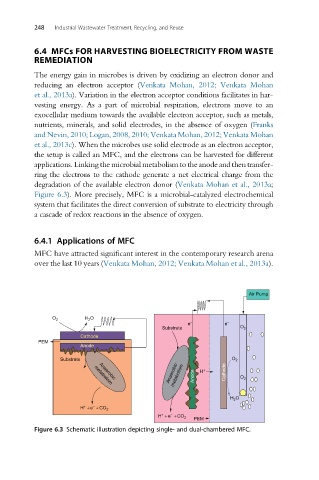
et al., 2013c). When the microbes use solid electrode as an electron acceptor,
the setup is called an MFC, and the electrons can be harvested for different
applications. Linking the microbial metabolism to the anode and then transfer-
ring the electrons to the cathode generate a net electrical charge from the
degradation of the available electron donor (Venkata Mohan et al., 2013a;
Figure 6.3). More precisely, MFC is a microbial-catalyzed electrochemical
system that facilitates the direct conversion of substrate to electricity through
a cascade of redox reactions in the absence of oxygen.
6.4.1 Applications of MFC
MFC have attracted significant interest in the contemporary research arena
over the last 10 years (Venkata Mohan, 2012; Venkata Mohan et al., 2013a).
Air Pump
H 2 O
O 2
− −
e e
Substrate O 2
Cathode
PEM
Anode
Substrate O 2
Anaerobic metabolism Anode H + Cathode O 2
Anaerobic
metabolism
H 2 O
+ −
H + e + CO 2
+ −
H + e + CO 2
PEM
Figure 6.3 Schematic illustration depicting single- and dual-chambered MFC.