
Page 139 - Injection Molding Advanced Troubleshooting Guide
P. 139
126 14 Mold Cooling
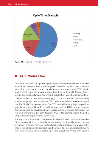
Figure 14.1 Example of cycle time breakdown
14.2 Water Flow
One of the key factors for optimizing cooling is to ensure turbulent flow within the
water lines. Turbulent flow is more capable of transferring heat than is laminar
water flow. It is vital to ensure that the temperature control unit (TCU) is ade-
quately sized to provide abundant water flow through the mold. If water flow is
lacking the resulting laminar flow will not transfer heat as well as turbulent flow.
Caution should be used when exchanging TCUs on a molding machine. Many
molding shops will have a variety of TCUs, often with different maximum capaci-
ties. If a 7-hp TCU is replaced with a 3-hp TCU the mold is not going to be provided
with the same level of flow. If the mold requires the 7-hp TCU to provide adequate
flow swapping to the smaller unit may lead to a variety of molding defects. For this
reason, it is important to clearly label all TCUs in the plant to ensure if a unit is
swapped it is swapped with the correct size.
The way to determine if water flow is turbulent is to calculate the Reynolds number
(Re). Equation 14.1 is the formula for calculating the Reynolds number for any
given flow condition. There are useful charts available that provide a quick refer-
ence to the minimum flow required based on water line size and coolant tempera-
ture; the processors who are analyzing cooling should be provided with these to