
Page 309 - Injection Molding Advanced Troubleshooting Guide
P. 309
31.3 Flow Lines Troubleshooting 303
have hesitation lines or even a blush-like appearance from the melt being forced
through the thin wall.
Always try to maintain uniform nominal wall stock. There have been cases where
even a 0.002–0.003 in difference in wall stock created a varying flow front that led
to a flow line. Short shot studies can help detect these types of problems. If the wall
stock must vary try to blend the surrounding wall stock to allow a better transition
into the thin section. Identify wall stock variation and be prepared to make process
adjustments to accommodate the design issues, but note that this will reduce the
process window for the mold. Run a flow analysis on the design prior to cutting
steel to look for areas of backfill and potential hesitation or non-filled areas. Making
changes on the CAD model is much more cost effective than adjusting steel after
the mold has been produced.
There may be cases where a flow leader or locally thickened area is needed on a
part to get adequate flow throughout a mold. Again this can be modeled in during
flow analysis to optimize the design prior to cutting steel. Remember when adding
flow leaders that they should be blended whenever possible to minimize read-
through on the class “A” surface.
31.3.2.2 Mold: Flow Pattern
There are cases when the flow pattern in the mold leads to flow lines. The location
of the gate determines how the mold will fill; it should be located to provide opti-
mized flow. If the flow length is too far from the gate the flow front will eventually
start to stall. A stalled flow front will lead to either a hesitation line or record
groove type of defect.
In a mold that is sequentially valve gated the downstream gates may surge into the
cavity when opened leading to flow defects on the part surface. If flow defects are
appearing when sequentially gating try adjusting the timing of the gate actuation
to determine if the defects are improved. Hot runner suppliers now offer modula-
tion of valve pin actuation that can offer some potential improvements of down-
stream gate defects.
In molds that violate nominal wall stock guidelines the flow pattern through the
varying wall stocks may yield meld lines that are called out as flow lines. These
meld lines will appear in the direction of flow and can be very subtle. Short shoot
the mold through the areas of concern to determine if a meld is occurring during
fill.
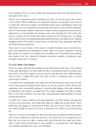
Figure 31.2 shows an example of a short shot showing an unbalanced flow progres-
sion which resulted in a meld line forming. This meld line was scrapped out as a
flow line, but it was only after running short shots that the true cause was under-
stood. Using STOP methodology, it was possible to systematically work through
this problem until the root cause was identified.