
Page 461 - Injection Molding Advanced Troubleshooting Guide
P. 461
46.3 Warp Troubleshooting 461
the outlet water is increasing above the recommended maximum the cooling cir-
cuits should be evaluated for the opportunity to split single long flow lengths into
multiple circuits.
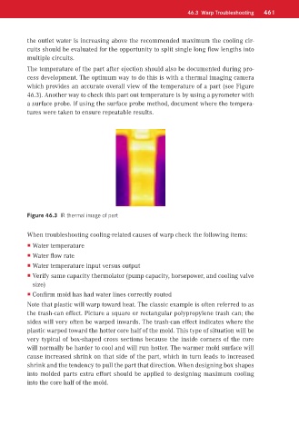
The temperature of the part after ejection should also be documented during pro-
cess development. The optimum way to do this is with a thermal imaging camera
which provides an accurate overall view of the temperature of a part (see Figure
46.3). Another way to check this part out temperature is by using a pyrometer with
a surface probe. If using the surface probe method, document where the tempera-
tures were taken to ensure repeatable results.
Figure 46.3 IR thermal image of part
When troubleshooting cooling-related causes of warp check the following items:
Water temperature
Water flow rate
Water temperature input versus output
Verify same capacity thermolator (pump capacity, horsepower, and cooling valve
size)
Confirm mold has had water lines correctly routed
Note that plastic will warp toward heat. The classic example is often referred to as
the trash-can effect. Picture a square or rectangular polypropylene trash can; the
sides will very often be warped inwards. The trash-can effect indicates where the
plastic warped toward the hotter core half of the mold. This type of situation will be
very typical of box-shaped cross sections because the inside corners of the core
will normally be harder to cool and will run hotter. The warmer mold surface will
cause increased shrink on that side of the part, which in turn leads to increased
shrink and the tendency to pull the part that direction. When designing box shapes
into molded parts extra effort should be applied to designing maximum cooling
into the core half of the mold.