
Page 166 - Innovations in Intelligent Machines
P. 166
158 S. Rathinam and R. Sengupta
C 2 /2+c 06
V 5
V -2
C 2 /2+c 04
c 56
c 45
V
4
V 6
C 2 /2+c 01
C 0 /2+c 06
c 34
C 0 /2+c 04
V 3
V
c 23 0 C 1 /2+c 04
C 0 /2+c 01
C 1 /2+c 06
V 2 V 1 (C 0 -C 1 )/2
c 12
(C 1 -C 2 )/2
C 1 /2+c 01
V -1
depot
destination
added vertices
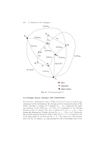
Fig. 11. Transformed graph G
3.3 Multiple Depot, Multiple TSP (MDMTSP)
Let there be n destinations and m UAVs. Let V be the set of vertices that
correspond to the destinations, the starting and the terminal location of the
UAVs. The first m vertices of V namely, V 1 ,...,V m , represents the start-
ing locations of the UAVs (i.e., the vertex V i corresponds to the starting
location of the i th vehicle). The next n vertices in V , V m+1 ,...,V m+n , rep-
resents the destinations. Finally, vertices V m+n+1 ,...,V 2m+n in V represents
the possible terminal locations of the UAVs. Let E = V × V denote the set
of all edges (pairs of vertices) and let c : E → + denote the cost function
with c(V i ,V j ) (or simply, c ij ) representing the cost of travelling from vertex