
Page 250 - Innovations in Intelligent Machines
P. 250
Toward Robot Perception through Omnidirectional Vision 243
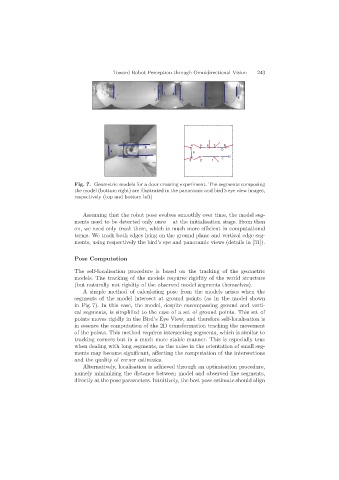
Fig. 7. Geometric models for a door crossing experiment. The segments composing
the model (bottom right) are illustrated in the panoramic and bird’s eye view images,
respectively (top and bottom left)
Assuming that the robot pose evolves smoothly over time, the model seg-
ments need to be detected only once – at the initialisation stage. From then
on, we need only track them, which is much more efficient in computational
terms. We track both edges lying on the ground plane and vertical edge seg-
ments, using respectively the bird’s eye and panoramic views (details in [31]).
Pose Computation
The self-localisation procedure is based on the tracking of the geometric
models. The tracking of the models requires rigidity of the world structure
(but naturally not rigidity of the observed model segments themselves).
A simple method of calculating pose from the models arises when the
segments of the model intersect at ground points (as in the model shown
in Fig. 7). In this case, the model, despite encompassing ground and verti-
cal segments, is simplified to the case of a set of ground points. This set of
points moves rigidly in the Bird’s Eye View, and therefore self-localisation is
in essence the computation of the 2D transformation tracking the movement
of the points. This method requires intersecting segments, which is similar to
tracking corners but in a much more stable manner. This is especially true
when dealing with long segments, as the noise in the orientation of small seg-
ments may become significant, affecting the computation of the intersections
and the quality of corner estimates.
Alternatively, localisation is achieved through an optimisation procedure,
namely minimizing the distance between model and observed line segments,
directly at the pose parameters. Intuitively, the best pose estimate should align