
Page 261 - Innovations in Intelligent Machines
P. 261
254 J. Gaspar et al.
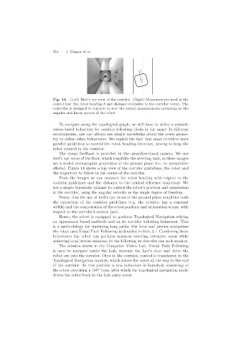
Fig. 14. (Left) Bird’s eye view of the corridor. (Right) Measurements used in the
control law: the robot heading θ and distance d relative to the corridor centre. The
controller is designed to regulate to zero the (error) measurements actuating on the
angular and linear speeds of the robot
To navigate along the topological graph, we still have to define a suitable
vision-based behaviour for corridor following (links in the map). In different
environments, one can always use simple knowledge about the scene geome-
try to define other behaviours. We exploit the fact that most corridors have
parallel guidelines to control the robot heading direction, aiming to keep the
robot centred in the corridor.
The visual feedback is provided by the omnidirectional camera. We use
bird’s eye views of the floor, which simplifies the servoing task, as these images
are a scaled orthographic projection of the ground plane (i.e. no perspective
effects). Figure 14 shows a top view of the corridor guidelines, the robot and
the trajectory to follow in the centre of the corridor.
From the images we can measure the robot heading with respect to the
corridor guidelines and the distance to the central reference trajectory. We
use a simple kinematic planner to control the robot’s position and orientation
in the corridor, using the angular velocity as the single degree of freedom.
Notice that the use of bird’s eye views of the ground plane simplifies both
the extraction of the corridor guidelines (e.g. the corridor has a constant
width) and the computation of the robot position and orientation errors, with
respect to the corridor’s central path.
Hence, the robot is equipped to perform Topological Navigation relying
on appearance based methods and on its corridor following behaviour. This
is a methodology for traversing long paths. For local and precise navigation
the robot uses Visual Path Following as detailed in Sect. 3.1. Combining these
behaviours the robot can perform missions covering extensive areas while
achieving local precise missions. In the following we describe one such mission.
The mission starts in the Computer Vision Lab. Visual Path Following
is used to navigate inside the Lab, traverse the Lab’s door and drive the
robot out into the corridor. Once in the corridor, control is transferred to the
Topological Navigation module, which drives the robot all the way to the end
of the corridor. At this position a new behaviour is launched, consisting of
◦
the robot executing a 180 turn, after which the topological navigation mode
drives the robot back to the Lab entry point.