
Page 266 - Innovations in Intelligent Machines
P. 266
Toward Robot Perception through Omnidirectional Vision 259
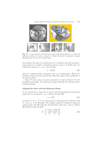
Fig. 17. (Top) original omnidirectional image and back-projection to a spherical
surface centred at the camera viewpoint. (Below) Examples of perspective images
obtained from the omnidirectional image
focal lengths. Denoting the transformation of coordinates from the omnidirec-
tional camera to a desired (rotated) perspective camera by R then the new
perspective image {p : p =(u, v, 1)} becomes:
p = λKRP (26)
where K contains intrinsic parameters and λ is a scaling factor. This is the
pin-hole camera projection model [25], when the origin of the coordinates is
the camera centre.
Figure 17 shows some examples of perspective images obtained from the
omnidirectional image. The perspective images illustrate the selection of the
viewing direction.
Aligning the Data with the Reference Frame
In the reconstruction algorithm we use the normalised perspective projection
model [25], by choosing K = I 3×3 in Eqs. (25) and (26):
p = λRP (27)
in which p =[uv 1] T is the image point, in homogeneous coordinates and
P =[xy z] T is the 3D point. The rotation matrix R is chosen to align the
camera frame with the reference (world) frame. Since the z axis is vertical,
the matrix R takes the form:
⎡ ⎤
cos(θ)sin(θ)0
R = ⎣ − sin(θ)cos(θ)0 ⎦ , (28)
0 0 1