
Page 268 - Innovations in Intelligent Machines
P. 268
Toward Robot Perception through Omnidirectional Vision 261
A P =0 3N . (31)
This system is solved in the total least-squares [39] sense by assigning to
P the singular vector of A corresponding to the smallest singular value. The
original vector of coordinates P is obtained from P by performing the inverse
of the operations that led from Eq. (30) to Eq. (31).
The reconstruction algorithm is easily extended to the case of multiple
cameras. The orientation of the cameras is estimated from vanishing points
as above and the projection model becomes:
p = λ(RP − Rt) (32)
where t is the position of the camera. It is zero for the first camera and is one
of t 1 ...t j if j additional cameras are present.
Considering for example that there are two additional cameras and follow-
ing the same procedure as for a single image, similar A and P are defined for
each camera. The problem has six new degrees of freedom corresponding to
the two unknown translations t 1 and t 2 :
⎡ ⎤
P 1
⎡ ⎤
A 1 ⎢ P 2 ⎥
⎢ ⎥
⎣ A 2 −A 2 .1 2 ⎦ ⎢ P 3 ⎥ = 0 (33)
⎢ ⎥
A 3 −A 3 .1 3 ⎣ t 1 ⎦
t 2
where 1 2 and 1 3 are matrices to stack the blocks of A 2 and A 3 .
As before co-linearity and co-planarity information is used to obtain a
reduced system. Note that columns corresponding to different images may be
combined, for example if a 3D point is tracked or if a line or plane spans
multiple images. The reduced system is solved in the total least-squares sense
and the 3D points P are retrieved as in the single-view case. The detailed
reconstruction method is given in [42].
Results
Our reconstruction method provides estimates of 3D points in the scene. In
order to visualise these estimates, facets are added to connect some of the 3D
points, as indicated by the user. Texture is extracted from the omnidirectional
images and a complete textured 3D model is obtained.
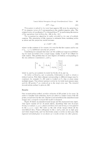
Figure 18 shows an omnidirectional image and the superposed user input.
This input consists of the 16 points shown, knowledge that sets of points
belong to constant x, y or z planes and that other sets belong to lines parallel
to the x, y or z axes. The table on the side of the images shows all the
user-defined data. Planes orthogonal to the x and y axes are in light gray
and white respectively, and one horizontal plane is shown in dark gray (the
topmost horizontal plane is not shown as it would occlude the other planes).