
Page 100 - Inorganic Mass Spectrometry : Fundamentals and Applications
P. 100
90 ~l~sik
ion kinetic energies 1-4 eV) for a single mass as well as over a wider range of
mass-dependent ion kinetic energies. Calculation of ion trajectories in order to
design optimal ion optics is complicated by two processes: space charge effects
and scattering of ions by collisions with the background gas, ~urthermore, the
location and distance over which charge separation occurs are critical and not well
known. Tanner has described the development of the ion optics for ICP-MS as a
combination of "modeling, intuition and blind luck" [ 1051.
High-energy photons and fast neutrals can produce signal if they strike the
a
detector. Two main approaches have been used to minimize this potential back-
a
ground signal. A stop can be placed on-axis and ions focused in path around or in
back of the stop. Alternatively, an offset ion lens can be used or the ions can be
directed through a 90" angle into the mass spectrometer to prevent a straight line
of sight between the sampler-skimmer and the mass spectrometer.
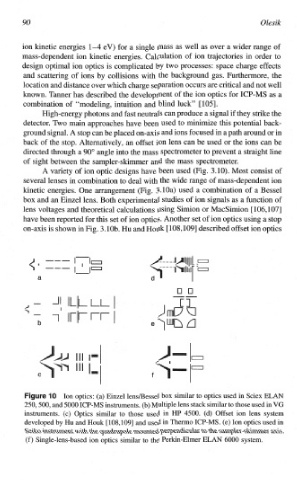
A variety of ion optic designs have been used (Fig. 3.10). Most consist of
several lenses in combination to deal with the wide range of mass-dependent ion
kinetic energies. One arrangement (Fig. 3.10a) used a combination of a Bessel
box and an Einzel lens. Both experimental studies of ion signals as a function of
lens voltages and theoretical calculations using Simion or MacSimion [106,107]
have been reported for this set of ion optics. Another set of ion optics using a stop
on-axis is shown in Fig. 3.10b. Hu and Houk [ 108,1091 described offset ion optics
a
L-L" I "
Cl
l-l- I Irmc7 U
b
Ion optics: (a) Einzel 1ensBessel box similar to optics used in Sciex ELM
250,500, and 5000 ICP-MS instruments. (b) Multiple lens stack similar to those used in VG
instruments. (c) Optics similar to those used in HP 4500. (d) Offset ion lens system
developed by Hu and Houk [ 108,1091 and used in Themo ICP-MS. (e) Ion optics used in
Seiko instrument with the quadrupole mounted perpendicular to the sample~-s~~er
axis.
(f) Single-lens-based ion optics similar to the Perkin-Elmer ELAN 6000 system.