
Page 102 - Inorganic Mass Spectrometry : Fundamentals and Applications
P. 102
92 Olesik
a C
1 .O
0.8
0.6
0.4
0.2
0.0
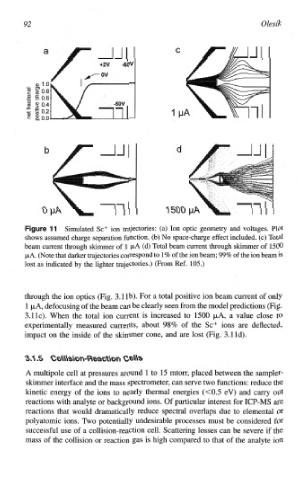
11 Simulated Sc+ ion trajectories: (a) Ion optic geometry and voltages. Plot
shows assumed charge separation function. (b) No space-charge effect included. (c) Total
beam current through skimmer of 1 p,A (d) Total beam current through skimer of 1500
PA. (Note that darker trajectories correspond to 1% of the ion beam; 99% of the ion beam is
lost as indicated by the lighter trajectories.) (From Ref. 105.)
through the ion optics (Fig. 3.1 1b). For a total positive ion beam current of only
l PA, defocusing of the beam can be clearly seen from the model predictions (Fig.
3. l IC). When the total ion current is increased to 1500 PA, a value close to
e~pe~mentally measured currents, about 98% of the Sc+ ions are deflected,
impact on the inside of the skimmer cone, and are lost (Fig. 3.1 Id).
A multipole cell at pressures around 1 to 15 mtorr, placed between the sampler-
skimer interfack and the mass spectrometer, can serve two functions: reduce
the
kinetic energy of the ions to nearly thermal energies (c0.5 eV) and carry out
reactions with analyte or background ions. Of particular interest for ICP-MS are
reactions that would dramatically reduce spectral overlaps due to elemental or
polyatomic ions. Two potentially undesirable processes must be considered for
successful use of a collision-reaction cell. Scattering losses can be severe if the
mass of the collision or reaction gas is high compared to that of the analyte ion