
Page 107 - Inorganic Mass Spectrometry : Fundamentals and Applications
P. 107
I~du~tively Coupled Plasma Mass ~pectromet~ 97
available. The main advantages of TOF-ICP-MS are due to the simultaneous
sampling of ions of all masses. As a result, transient signals for all elements and
isotopes can be monitored with high temporal resolution. Because ions are ex-
tracted and injected into the TOF-MS simultaneously, high-precision isotope
ratios and analyte/internal standard ratios should be attainable. Ion trap mass
spectrometers have been used in combination with a quadrupole mass filter and
alone with an ICP ion source [ 129- 1331. Initially the large ratio of Ar+ to analyte
ions in the ICP was thought to make ion trap mass spectrometers impractical
because of the limited total number of ions that can be stored in the trap. However,
the number of Ar+ ions observed in the ion trap is orders of magnitude less, on a
relative basis, than in the ICP itself.
High-resolution Fourier transform ion cyclotron resonance mass spectrome-
ters have also been used for ICP-MS [ 134,1351. Quadrupole mass spectrometers
also
used in alternate stability regions to obtain higher resolution than typical have
been used for ICP-MS [136,137].
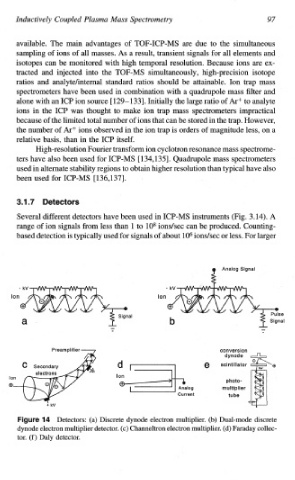
Several different detectors have been used in ICP-MS inst~ments (Fig. 3.14). A
range of ion signals from less than 1 to lo8 iondsec can be produced. Counting-
based detection is typically used for signals of about lo6 ionslsec or less. For larger
Ion Ion
ai e
al
Preamplifier 7 conversion
dynode ,-j-,
e scintillator L
>
*
+
lo I photo-
I on
0" 0
multiplier
Current tube
kV
Figure 14 Detectors: (a) Discrete dynode electron multiplier. (b) Dual-mode discrete
dynode electron multiplier detector. (c) Channeltron electron multiplier. (d) Faraday collec-
tor. (f) Daly detector.