
Page 121 - Inorganic Mass Spectrometry : Fundamentals and Applications
P. 121
Inductively Coupled Plasma Mass Spectrometry 111
Center (~ebulizer) Gas Flow Rate, Applied Power, and
Depth
~ampli~~
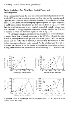
For a particular instrument the most influential experimental parameters are the
applied ICP power, the nebulizer (center) gas flow rate, and the sampling depth
(typically described as the distance from the sampling orifice the end of the load
to
coil) [155, 1561. For a particular sampling depth and power, the signal magnitude
is highly dependent on the nebulizer gas flow rate, as shown in Fig. 3.16. There-
fore, the nebulizer gas must be very precisely controlled, typically using a mass
flow controller. If the applied power is increased, a higher nebulizer gas flow rate
is required to obtain the maximum signal, as seen in Fig. 3.16,
To a first approximation, this behavior can understood by considering the
be
processes that a drop of sample undergoes in the ICP (Fig. 3.2) and the main
effects of a change in nebulizer gas flow rate on the plasma. After the sample
aerosol exits the center tube of the torch, it travels a short distance (2 to 10 m)
before it enters the plasma's center channel. As the nebulizer gas flow rate is
increased, the location where the plasma begins (and the temperature increases
for
rapidly) in the center of the plasma moves downstream (Fig. 3.17). Therefore,
600 I 1
0.90 1.00 1.10 1.20 1.30 1.40 0.90 1.00 1.10 1.20 1.30 1.40
Nebulizer gas flow rate (Llmin) Nebulizer gas flow rate (Lfmin)
400 8000
1.5 kW 7000
h A
h 300 5 6000
CV) I
C O 5 5000
3 r
O
g
__I v m g 200 v 4000
- 0
m = ?ii 3000
.E) tloo .E? 2000
U) CO
1000
0 n
0.90 1.00 1.io 1.20 1.30 1.40 0.90 1.00 1.10 1.20 1.30 1.40
Nebulizer gas flow rate (Lfmin) Nebulizer gas flow rate (L/min)
Effect of nebulizer gas flow rate and power on Na+, Ti+, W+, and Bi+ ICP-MS
signals. (From Ref. 156.)