
Page 210 - Solutions Manual to accompany Electric Machinery Fundamentals
P. 210
(c) If the speed of the rotor were increased to 550 rad/s, the induced voltage of the loop would increase
to
e ind 2rlB
e ind 2 0.25 m 0.5 m 0.4 T 550 rad/s 55 V
and the current flow out of the machine will increase to
e V 55 V 48 V
i ind B 17.5 A
R 0.4
(d) If the speed of the rotor were decreased to 450 rad/s, the induced voltage of the loop would fall to
e ind 2rlB
e ind 2 0.25 m 0.5 m 0.4 T 450 rad/s 45 V
Here, e ind is less than V , so current flows into the loop and the machine is acting as a motor. The current
B
flow into the machine would be
V e 48 V 45 V
i B ind 7.5 A
R 0.4
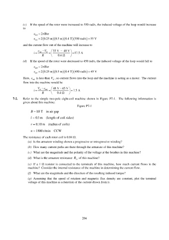
7-2. Refer to the simple two-pole eight-coil machine shown in Figure P7-1. The following information is
given about this machine:
Figure P7-1
B 10. T in air gap
.
l 03 m (length of coil sides)
r . 0 10 m (radius of coils)
n 1800 r/min CCW
The resistance of each rotor coil is 0.04 .
(a) Is the armature winding shown a progressive or retrogressive winding?
(b) How many current paths are there through the armature of this machine?
(c) What are the magnitude and the polarity of the voltage at the brushes in this machine?
(d) What is the armature resistance R A of this machine?
(e) If a 1 resistor is connected to the terminals of this machine, how much current flows in the
machine? Consider the internal resistance of the machine in determining the current flow.
(f) What are the magnitude and the direction of the resulting induced torque?
(g) Assuming that the speed of rotation and magnetic flux density are constant, plot the terminal
voltage of this machine as a function of the current drawn from it.
204