
Page 212 - Solutions Manual to accompany Electric Machinery Fundamentals
P. 212
(d) There are 8 coils on this machine in two parallel paths, with each coil having a resistance of 0.04 .
Therefore, the total resistance R is
A
0.04 0.04 0.04 0.04 0.04 0.04 0.04 0.04
R 0.04 0.04 0.04 0.04 0.04 0.04 0.04 0.04
A
R A 0.08
(e) The voltage produced by this machine is 33.9 V, as found in part (c). Therefore, the current
flowing in the machine will be
E 33.9 V
I A 31.4 A
A
R A R load 0.08 1.0
(f) The induced torque is given by Equation 7-46:
ZrlBI 12 cond 0.10 m 0.3 m 1.0 T 33.9 A
A
ind
a 2 current paths
ind 4.12 N m, CW (opposite to the direction of rotation)
(e) The terminal voltage of this machine is given by
V T E A I R A
A
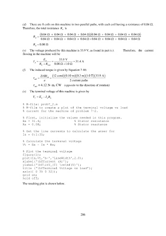
% M-file: prob7_2.m
% M-file to create a plot of the terminal voltage vs load
% current for the machine of problem 7-2.
% First, initialize the values needed in this program.
Ea = 31.4; % Stator resistance
Ra = 0.08; % Stator reactance
% Get the line currents to calculate the anser for
Ia = 0:1:35;
% Calculate the terminal voltage
Vt = Ea - Ia * Ra;
% Plot the terminal voltage
figure(1);
plot(Ia,Vt,'b-','LineWidth',2.0);
xlabel('\bfCurrent (A)');
ylabel('\bf\itV_{T} \rm\bf(V)');
title ('\bfTerminal Voltage vs Load');
axis([ 0 35 0 32]);
grid on;
hold off;
The resulting plot is shown below.
206