
Page 26 - Solutions Manual to accompany Electric Machinery Fundamentals
P. 26
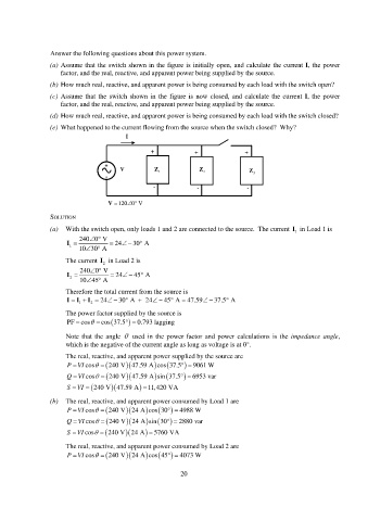
Answer the following questions about this power system.
(a) Assume that the switch shown in the figure is initially open, and calculate the current I, the power
factor, and the real, reactive, and apparent power being supplied by the source.
(b) How much real, reactive, and apparent power is being consumed by each load with the switch open?
(c) Assume that the switch shown in the figure is now closed, and calculate the current I, the power
factor, and the real, reactive, and apparent power being supplied by the source.
(d) How much real, reactive, and apparent power is being consumed by each load with the switch closed?
(e) What happened to the current flowing from the source when the switch closed? Why?
I
+ + +
+
V Z 1 Z 2 Z
- 3
- - -
V 120 0 V
SOLUTION
(a) With the switch open, only loads 1 and 2 are connected to the source. The current in Load 1 is
I
1
240 0 V
I 24 30 A
1
10 30 A
The current I 2 in Load 2 is
240 0 V
I 24 45 A
2
10 45 A
Therefore the total current from the source is
I 1 I 2 I 24 30 A 24 45 A 47.59 37.5 A
The power factor supplied by the source is
PF cos cos 37.5 0.793 lagging
Note that the angle used in the power factor and power calculations is the impedance angle,
which is the negative of the current angle as long as voltage is at 0°.
The real, reactive, and apparent power supplied by the source are
PVI cos 240 V 47.59 A cos 37.5 9061 W
QVI cos 240 V 47.59 A sin 37.5 6953 var
SVI 240 V 47.59 A 11,420 VA
(b) The real, reactive, and apparent power consumed by Load 1 are
PVI cos 240 V 24 A cos 30 4988 W
QVI cos 240 V 24 A sin 30 2880 var
SVI cos 240 V 24 A 5760 VA
The real, reactive, and apparent power consumed by Load 2 are
PVI cos 240 V 24 A cos 45 4073 W
20