
Page 276 - Integrated Wireless Propagation Models
P. 276
254 C h a p t e r F o u r
Base station
Final building
d
FIGURE 4.5.5.3.2.1 M u l tiple i ffraction over building rooftops.
<J
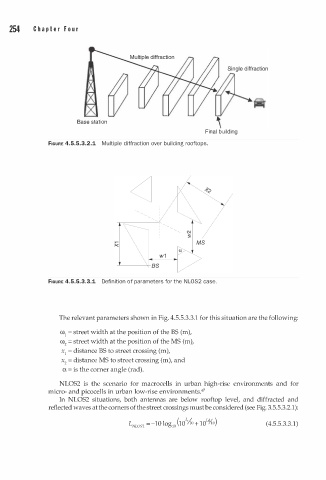
FIGURE 4.5.5.3.3.1 Definition of parameters for the N L OS2 case.
The relevant parameters shown in Fig. 4.5.5.3.3.1 for this situation are the following:
ro1 = street width at the position of the BS (m),
ro = street width at the position of the MS (m),
2
x1 = distance BS to street crossing (m),
x = distance MS to street crossing (m), and
2
a = is the corner angle (rad).
NLOS2 is the scenario for macrocells in urban high-rise environments and for
micro- and picocells in urban low-rise environments.47
In NLOS2 situations, both antennas are below rooftop level, and diffracted and
reflected waves at the corners of the street crossings must be considered (see Fig. 3.5.5.3.2.1 ) :
L o
o
1
L N OS = - 10 log (10 ;{ + 10 L � ) (4.5.5.3.3.1)
0
L 2