
Page 76 - Intelligent Communication Systems
P. 76
CHAPTER 7/NEWLY DEVELOPED TELECOMMUNICATION SERVICES 59
In the bus network, each node is linked to a bus that is common to all nodes.
The information issued by a node is transmitted via the bus. Coaxial cable is mainly
used for the bus network. Every node has its communication function. Even when
a node is in trouble, it produces no negative effects on other nodes. Therefore the
network is reliable. And the network structure is easily changed and expanded. Any
node can be linked to the bus at any time. Many channels can be accommodated
in this network by supplying the different carrier frequencies to make it a
broadband network. However, the network is low on the security of the data trans-
mitted among nodes. Finally, when the bus is in trouble, all of the traffic goes
wrong.
In the ring network, twisted-pair cables or optical-fiber cables are used. One-
way transmission is allowed in this system. The network is a closed one, and each
node is in sequence. When a node in the ring issues a message into the network, it
is transmitted via the ring until the message returns to the original node. The mes-
sage becomes distorted while running through the ring. But each node that receives
it reproduces and passes it to the adjacent node. Therefore the distance of the ring
can be expanded. The bus and ring networks act as multicast transmission systems.
That is, any node in the network can issue a message and receive it. By introduc-
ing adequate access control technology, some kinds of switching and broadcast-
ing functions can be achieved.
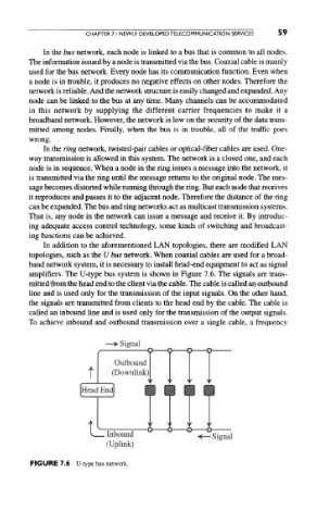
In addition to the aforementioned LAN topologies, there are modified LAN
topologies, such as the U bus network. When coaxial cables are used for a broad-
band network system, it is necessary to install head-end equipment to act as signal
amplifiers. The U-type bus system is shown in Figure 7.6. The signals are trans-
mitted from the head end to the client via the cable. The cable is called an outbound
line and is used only for the transmission of the input signals. On the other hand,
the signals are transmitted from clients to the head end by the cable. The cable is
called an inbound line and is used only for the transmission of the output signals.
To achieve inbound and outbound transmission over a single cable, a frequency
FIGURE 7.6 U-type bus network.