
Page 387 - Intelligent Digital Oil And Gas Fields
P. 387
326 Intelligent Digital Oil and Gas Fields
without needing to miniaturize continually the circuits. These new chips
enable image processing, image recognition, self-driving cars, virtual reality
(VR), and artificial intelligence.
9.1.1 Nanosensors
Nanotechnology refers to miniaturizing technology to a nanoscale so that it
can be used in remote places where conventional sensors do not work, like
deep in reservoirs. Naturally, O&G operations have plenty of situations
where nanotechnologies can be used and will benefit DOF solutions.
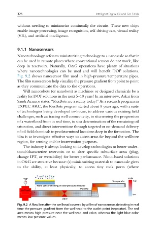
Fig. 9.2 shows nanosensor film used in high-pressure/temperature pipes.
The film nanosensors help visualize the pressure gradient from point to point
as they communicate the data to the operations.
Will nanorobots (or nanobots) as machines or designed chemicals be a
reality for DOF solutions in the next 5–10 years? In an interview, Askar from
Saudi Aramco states, “ResBots are a reality today!” As a research program in
EXPEC ARC, the ResBots program started about 8 years ago, with a suite
of technologies being developed in-house, to address various existing field
challenges, such as: tracing well connectivity, in situ sensing the progression
of a waterflood front in real time, in situ determination of the remaining oil
saturation, and direct interventions through targeted or on-demand delivery
of oil field chemicals to predetermined locations deep in the formation. The
idea is to investigate effective ways to access areas far beyond the wellbore
region, for sensing and/or intervention purposes.
The industry is always looking to develop technologies to better under-
stand/characterize reservoirs or to alter specific subsurface areas (plug,
change IFT, or wettability) for better performance. Nano-based solutions
in O&G are attractive because: (a) miniaturizing materials to nanoscale gives
us the ability, at least physically, to access tiny rock pores (where
THP scale
To separator High
Nano sensor showing in color pressure indicator
Pipeline
wellhead
low
Valve
Fig. 9.2 A flow line after the wellhead covered by a film of nanosensors detecting in real
time the pressure gradient from the wellhead to the outlet point (separator). The red
area means high pressure near the wellhead and valve, whereas the light blue color
means low-pressure values.