
Page 146 - Intro Predictive Maintenance
P. 146
Vibration Monitoring and Analysis 137
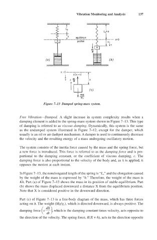
Figure 7–13 Damped spring-mass system.
Free Vibration—Damped. A slight increase in system complexity results when a
damping element is added to the spring-mass system shown in Figure 7–13. This type
of damping is referred to as viscous damping. Dynamically, this system is the same
as the undamped system illustrated in Figure 7–12, except for the damper, which
usually is an oil or air dashpot mechanism. A damper is used to continuously decrease
the velocity and the resulting energy of a mass undergoing oscillatory motion.
The system consists of the inertia force caused by the mass and the spring force, but
a new force is introduced. This force is referred to as the damping force and is pro-
portional to the damping constant, or the coefficient of viscous damping, c. The
damping force is also proportional to the velocity of the body and, as it is applied, it
opposes the motion at each instant.
In Figure 7–13, the nonelongated length of the spring is “L o” and the elongation caused
by the weight of the mass is expressed by “h.” Therefore, the weight of the mass is
Kh. Part (a) of Figure 7–13 shows the mass in its position of stable equilibrium. Part
(b) shows the mass displaced downward a distance X from the equilibrium position.
Note that X is considered positive in the downward direction.
Part (c) of Figure 7–13 is a free-body diagram of the mass, which has three forces
acting on it. The weight (Mg/g c), which is directed downward, is always positive. The
Ê dX ˆ
damping force c , which is the damping constant times velocity, acts opposite to
Ë dt ¯
the direction of the velocity. The spring force, K(X + h), acts in the direction opposite