
Page 152 - Intro Predictive Maintenance
P. 152
Vibration Monitoring and Analysis 143
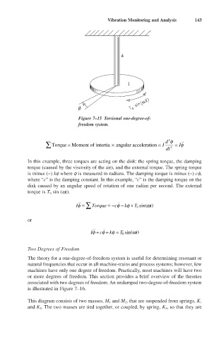
Figure 7–15 Torsional one-degree-of-
freedom system.
2
d f
 Torque = Moment of intertia angular acceleration = I = If ˙˙
¥
dt 2
In this example, three torques are acting on the disk: the spring torque, the damping
torque (caused by the viscosity of the air), and the external torque. The spring torque
is minus (-) kf where f is measured in radians. The damping torque is minus (-) cf,
where “c” is the damping constant. In this example, “c” is the damping torque on the
disk caused by an angular speed of rotation of one radian per second. The external
torque is T 0 sin (wt).
˙
˙˙
If = Â Torque = - cf - kf + T sin w t
()
0
or
˙˙
˙
()
If + cf + kf = T sin w t
0
Two Degrees of Freedom
The theory for a one-degree-of-freedom system is useful for determining resonant or
natural frequencies that occur in all machine-trains and process systems; however, few
machines have only one degree of freedom. Practically, most machines will have two
or more degrees of freedom. This section provides a brief overview of the theories
associated with two degrees of freedom. An undamped two-degree-of-freedom system
is illustrated in Figure 7–16.
This diagram consists of two masses, M 1 and M 2 , that are suspended from springs, K 1
and K 2 . The two masses are tied together, or coupled, by spring, K 3 , so that they are