
Page 140 - Intro to Space Sciences Spacecraft Applications
P. 140
127
Communications
baseband signal, carrier wave, and the resulting ASK signal are shown in
Figure 5-12.
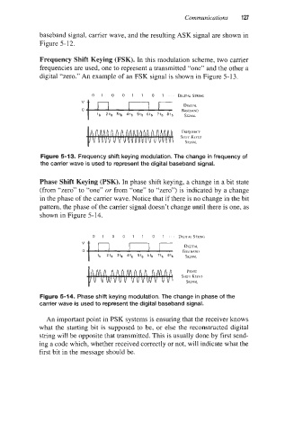
Frequency Shift Keying (FSK). In this modulation scheme, two carrier
frequencies are used, one to represent a transmitted “one” and the other a
digital “zero.” An example of an FSK signal is shown in Figure 5-1 3.
0 1 0 0 1 1 0 1 - DIGITALSTRING
FREQUENCY
SfflFT KEYED
SlCNAL
Figure 5-13. Frequency shift keying modulation. The change in frequency of
the carrier wave is used to represent the digital baseband signal.
Phase Shift Keying (PSK). In phase shift keying, a change in a bit state
(from “zero” to “one” or from “one” to “zero”) is indicated by a change
in the phase of the carrier wave. Notice that if there is no change in the bit
pattern, the phase of the carrier signal doesn’t change until there is one, as
shown in Figure 5-14.
PHASE
SHIFT KEYEU
SICNAL
Figure 5-14. Phase shift keying modulation. The change in phase of the
carrier wave is used to represent the digital baseband signal.
An important point in PSK systems is ensuring that the receiver knows
what the starting bit is supposed to be, or else the reconstructed digital
string will be opposite that transmitted. This is usually done by first send-
ing a code which, whether received correctly or not, will indicate what the
first bit in the message should be.