
Page 137 - Intro to Space Sciences Spacecraft Applications
P. 137
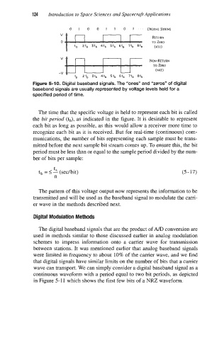
’   0   1   0   0   1   1   0   1   . .  DIGITAL STRING
                            Introduction to Space Sciences and Spacecraft Applications
                      124
                                                                     RETURN
                                  b  & &                             TO (RTz) ZERO


                                                                     TO ZERO
                                                                      ( NRZ )
                                -V k=f-= 5th  4tb  5tb  6tb  7tb  8tb   NoN-RETURN
                                          2tb
                                       tb
                      Figure 5-1 0. Digital baseband signals. The “ones” and “zeros” of digital
                      baseband signals are usually represented by voltage levels held for a
                      specified period of time.


                        The time that the specific voltage is held to represent each bit is called
                      the bit period  (tb), as indicated in the figure. It is desirable to represent
                      each bit as long as possible, as this would allow a receiver more time to
                      recognize each bit as it is received. But for real-time (continuous) com-
                      munications, the number of bits representing each sample must be trans-
                      mitted before the next sample bit stream comes up. To ensure this, the bit
                      period must be less than or equal to the sample period divided by the num-
                      ber of bits per sample:
                              t
                        tb = 5 2 (sec/bit)                                       (5 - 17)
                               n


                        The pattern of this voltage output now represents the information to be
                      transmitted and will be used as the baseband signal to modulate the carri-
                      er wave in the methods described next.

                      Digital Modulation Methods

                        The digital baseband signals that are the product of A/D conversion are
                      used in methods similar to those discussed earlier in analog modulation
                      schemes to  impress  information  onto  a  carrier  wave  for  transmission
                      between  stations. It was mentioned earlier that analog baseband signals
                      were limited in frequency to about 10% of the carrier wave, and we find
                      that digital signals have similar limits on the number of bits that a carrier
                      wave can transport. We can simply consider a digital baseband signal as a
                      continuous waveform with a period equal to two bit periods, as depicted
                      in Figure 5-1 1 which shows the first few bits of a NRZ waveform.