
Page 150 - Intro to Space Sciences Spacecraft Applications
P. 150
Remote Sensing 137
Geometry of Remote Sensing
The basic geometrical relationships between a satellite and the earth
were described in Chapter 2. These are reproduced, along with some of
the geometry specific to remote sensing, in Figure 6- 1.
The right side of the figure displays the angles described in Chapter 2
associated with the angular field of view (Q) which represents the maxi-
mum angular distance visible from the satellite when the remote sensor’s
view is tangential to the earth’s surface. The maximum field of view
(FOV) can be described as the total curved earth area visible from horizon
to horizon by an observation in space, associated with the swath width
distance described in Chapter 2. In most cases, a remote sensor concen-
trates its instantaneous observation on a small portion of the total field of
view using a lens, antenna, or some similar method of focusing incoming
energy. This smaller area observed by the sensor at a particular time is
known as the instantaneousfield ufview (IFOV) and will be described in
more detail shortly.
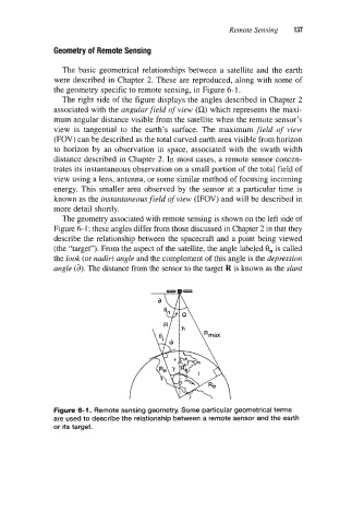
The geometry associated with remote sensing is shown on the left side of
Figure 6- 1 ; these angles differ from those discussed in Chapter 2 in that they
describe the relationship between the spacecraft and a point being viewed
(the “target”). From the aspect of the satellite, the angle labeled 8, is called
the bok (or nadir) angle and the complement of this angle is the depression
angle (a). The distance from the sensor to the target R is known as the slant
Figure 6-1. Remote sensing geometry. Some particular geometrical terms
are used to describe the relationship between a remote sensor and the earth
or its target.