
Page 71 - Intro to Space Sciences Spacecraft Applications
P. 71
Introduction to Space Sciences and Spacecraft Applications
58
n
-
NOZZLE P
00
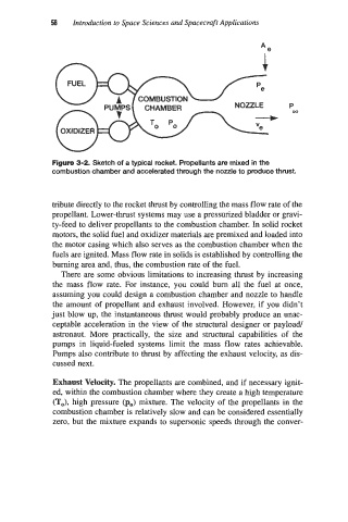
Figure 3-2. Sketch of a typical rocket. Propellants are mixed in the
combustion chamber and accelerated through the nozzle to produce thrust.
tribute directly to the rocket thrust by controlling the mass flow rate of the
propellant. Lower-thrust systems may use a pressurized bladder or gravi-
ty-feed to deliver propellants to the combustion chamber. In solid rocket
motors, the solid fuel and oxidizer materials are premixed and loaded into
the motor casing which also serves as the combustion chamber when the
fuels are ignited. Mass flow rate in solids is established by controlling the
burning area and, thus, the combustion rate of the fuel.
There are some obvious limitations to increasing thrust by increasing
the mass flow rate. For instance, you could bum all the fuel at once,
assuming you could design a combustion chamber and nozzle to handle
the amount of propellant and exhaust involved. However, if you didn't
just blow up, the instantaneous thrust would probably produce an unac-
ceptable acceleration in the view of the structural designer or payload
astronaut. More practically, the size and structural capabilities of the
pumps in liquid-fueled systems limit the mass flow rates achievable.
Pumps also contribute to thrust by affecting the exhaust velocity, as dis-
cussed next.
Exhaust Velocity. The propellants are combined, and if necessary ignit-
ed, within the combustion chamber where they create a high temperature
(TJ, high pressure (p,) mixture. The velocity of the propellants in the
combustion chamber is relatively slow and can be considered essentially
zero, but the mixture expands to supersonic speeds through the conver-