
Page 113 - Introduction to Autonomous Mobile Robots
P. 113
Chapter 4
98
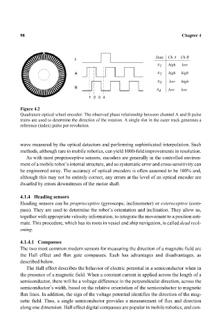
State Ch A Ch B
s 1 high low
s 2 high high
s 3 low high
s 4 low low
Figure 4.2
Quadrature optical wheel encoder: The observed phase relationship between channel A and B pulse
trains are used to determine the direction of the rotation. A single slot in the outer track generates a
reference (index) pulse per revolution.
wave measured by the optical detectors and performing sophisticated interpolation. Such
methods, although rare in mobile robotics, can yield 1000-fold improvements in resolution.
As with most proprioceptive sensors, encoders are generally in the controlled environ-
ment of a mobile robot’s internal structure, and so systematic error and cross-sensitivity can
be engineered away. The accuracy of optical encoders is often assumed to be 100% and,
although this may not be entirely correct, any errors at the level of an optical encoder are
dwarfed by errors downstream of the motor shaft.
4.1.4 Heading sensors
Heading sensors can be proprioceptive (gyroscope, inclinometer) or exteroceptive (com-
pass). They are used to determine the robot’s orientation and inclination. They allow us,
together with appropriate velocity information, to integrate the movement to a position esti-
mate. This procedure, which has its roots in vessel and ship navigation, is called dead reck-
oning.
4.1.4.1 Compasses
The two most common modern sensors for measuring the direction of a magnetic field are
the Hall effect and flux gate compasses. Each has advantages and disadvantages, as
described below.
The Hall effect describes the behavior of electric potential in a semiconductor when in
the presence of a magnetic field. When a constant current is applied across the length of a
semiconductor, there will be a voltage difference in the perpendicular direction, across the
semiconductor’s width, based on the relative orientation of the semiconductor to magnetic
flux lines. In addition, the sign of the voltage potential identifies the direction of the mag-
netic field. Thus, a single semiconductor provides a measurement of flux and direction
along one dimension. Hall effect digital compasses are popular in mobile robotics, and con-