
Page 140 - Introduction to Autonomous Mobile Robots
P. 140
Perception
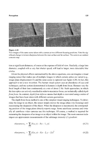
Figure 4.20 125
Two images of the same scene taken with a camera at two different focusing positions. Note the sig-
nificant change in texture sharpness between the near surface and far surface. The scene is an outdoor
concrete step.
tion at significant distances, of course at the expense of field of view. Similarly, a large lens
diameter, coupled with a very fast shutter speed, will lead to larger, more detectable blur
circles.
Given the physical effects summarized by the above equations, one can imagine a visual
ranging sensor that makes use of multiple images in which camera optics are varied (e.g.,
δ
image plane displacement ) and the same scene is captured (see figure 4.20). In fact, this
approach is not a new invention. The human visual system uses an abundance of cues and
techniques, and one system demonstrated in humans is depth from focus. Humans vary the
focal length of their lens continuously at a rate of about 2 Hz. Such approaches, in which
the lens optics are actively searched in order to maximize focus, are technically called depth
from focus. In contrast, depth from defocus means that depth is recovered using a series of
images that have been taken with different camera geometries.
The depth from focus method is one of the simplest visual ranging techniques. To deter-
mine the range to an object, the sensor simply moves the image plane (via focusing) until
maximizing the sharpness of the object. When the sharpness is maximized, the correspond-
ing position of the image plane directly reports range. Some autofocus cameras and virtu-
ally all autofocus video cameras use this technique. Of course, a method is required for
measuring the sharpness of an image or an object within the image. The most common tech-
I
niques are approximate measurements of the subimage intensity () gradient:
1 ∑
,
(
(
,
sharpness = Ixy) – Ix – 1 y) (4.21)
,
xy
2 ∑ ( ( , ( , 2)) 2
sharpness = Ixy) – Ix – 2 y – (4.22)
,
xy