
Page 421 - Introduction to Information Optics
P. 421
406 7. Pattern Recognition with Optics
for which we have
(7.58)
bt
It can be written as
(7,59)
in which the shift tolerance of the target is inversely proportional to the square
root of the thickness of the PR filter. Since the reflection filter has very high
angular selectivities, the target-shift limitation is somewhat sensitive to the
target translation. In other words, by making the thickness, t, sufficiently small
the shift tolerance in an RC can be made sufficiently high. Nevertheless,
reducing the thickness of the PR filter also decreases storage capacity.
3
To demonstrate the shift tolerance of the RC, a 1 cm Ce:Fe doped LiNbO 3
crystal has been used for the reflection-type matched-filter synthesis. By tuning
the wavelength at A/t = 0.1 nm per step with 10 sec per exposure, a set of
wavelength-multiplexed reflection-type matched filters is synthesized. After
constructing the PR filter, an input target can be used to reconstruct the
reference beam by simply scanning the wavelength of the light source. If the
input target is matched with one of the recorded matched filters, a sharp
correlation peak can be detected by a CCD camera. Thus, we see that
multitarget detection can be done by tuning the wavelength of the light source
so that the spectral contents of the multiplexed filter can be exploited.
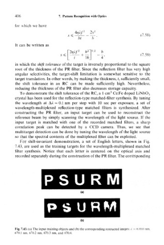
For shift-invariant demonstration, a set of English letters, shown in Fig.
7.43, are used as the training targets for the wavelength-multiplexed matched
filter synthesis. Notice that each letter is centered on the optical axis and
recorded separately during the construction of the PR filter. The corresponding
Fig, 7,43. (a) The input training objects and (b) the corresponding restructed images: / — 670.0 nm,
670.1 nm. 670.2 nm, 670.3 nm, and 670.4.