
Page 417 - Introduction to Information Optics
P. 417
402 7. Pattern Recognition with Optics
laser
M
CCDs
MICROCOMPUTER
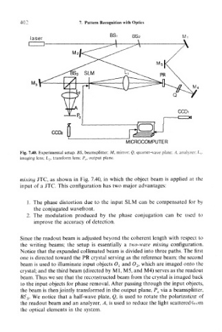
Fig. 7.40. Experimental setup. BS, beamsplitter; A/, mirror; Q, quarter-wave plate; A, analyzer: /_,,
imaging lens; L 2, transform lens; P,,, output plane.
mixing JTC, as shown in Fig. 7.40, in which the object beam is applied at the
input of a JTC. This configuration has two major advantages:
1, The phase distortion due to the input SLM can be compensated for by
the conjugated wavefront.
2. The modulation produced by the phase conjugation can be used to
improve the accuracy of detection.
Since the readout beam is adjusted beyond the coherent length with respect to
the writing beams; the setup is essentially a two-wave mixing configuration.
Notice that the expanded collimated beam is divided into three paths. The first
one is directed toward the PR crystal serving as the reference beam; the second
beam is used to illuminate input objects O t and 0 2, which are imaged onto the
crystal; and the third beam (directed by Ml, M5, and M4) serves as the readout
beam. Thus we see that the reconstructed beam from the crystal is imaged back
to the input objects for phase removal. After passing through the input objects,
the beam is then jointly transformed in the output plane, P 0 via a beamsplitter,
BS 3. We notice that a half-wave plate, Q, is used to rotate the polarization of
the readout beam and an analyzer, A, is used to reduce the light scattered from
the optical elements in the system.