
Page 439 - Introduction to Information Optics
P. 439
424 7. Pattern Recognition with Optics
OD
g(mx,my)
B5
BS2
\ 1 V
^ Relay & LCTV SLM
Expander f(x,y) Detector
BS4 A !*• Ar~^-^ BS5 A
3S3 \ \ . ,N f ^
s 1 I — ^ I L/
^ V L.
FL1 FL2 [„ / ^ FL3
/
\
M,\ ' ^ 2
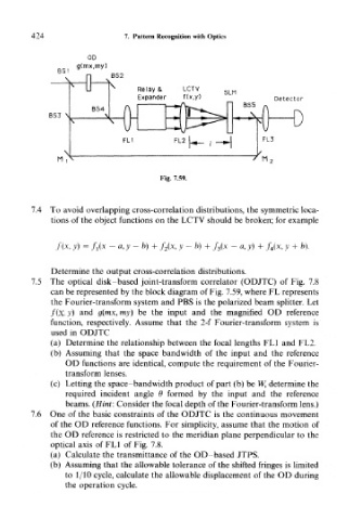
Fig. 7.59.
7.4 To avoid overlapping cross-correlation distributions, the symmetric loca-
tions of the object functions on the LCTV should be broken; for example
f(x, y) = fi(x -a,y-b) + f 2(x, y - b) + f 3(x - a, y) + / 4(,x, y + b).
Determine the output cross-correlation distributions.
7.5 The optical disk-based joint-transform correlator (ODJTC) of Fig. 7.8
can be represented by the block diagram of Fig. 7.59, where FL represents
the Fourier-transform system and PBS is the polarized beam splitter. Let
f(x, y) and g(mx, my) be the input and the magnified OD reference
function, respectively. Assume that the 2-f Fourier-transform system is
used in ODJTC
(a) Determine the relationship between the focal lengths FL1 and FL2.
(b) Assuming that the space bandwidth of the input and the reference
OD functions are identical, compute the requirement of the Fourier-
transform lenses.
(c) Letting the space-bandwidth product of part (b) be W, determine the
required incident angle 6 formed by the input and the reference
beams. (Hint: Consider the focal depth of the Fourier-transform lens.)
7.6 One of the basic constraints of the ODJTC is the continuous movement
of the OD reference functions. For simplicity, assume that the motion of
the OD reference is restricted to the meridian plane perpendicular to the
optical axis of FL1 of Fig. 7.8.
(a) Calculate the transmittance of the OD-based JTPS.
(b) Assuming that the allowable tolerance of the shifted fringes is limited
to 1/10 cycle, calculate the allowable displacement of the OD during
the operation cycle.