
Page 447 - Introduction to Information Optics
P. 447
432 7. Pattern Recognition with Optics
plot SCD as function of character number for o — 60 and a = 100,
respectively.
(c) Comment on the results obtained in part (b).
7.35 Assume that a 10-mm-thick LiNbO 3 photorefractive crystal is used for
a transmission-type hologram, and that the wavelength of the light source
A = 514 nm and the writing angle is about 45°.
(a) Compute the allowable reading angular deviation.
(b) Repeat part (a) for a reflection-type hologram.
(c) Draw a vector diagram to represent the reading direction for the
two-grating structure in a photorefractive crystal using the same
reading wavelength. Assume the same amplitude is used and that the
angular separation is denoted by A0.
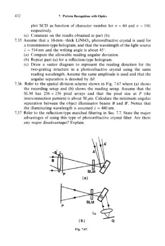
7.36. Refer to the spatial division scheme shown in Fig. 7.67 where (a) shows
the recording setup and (b) shows the reading setup. Assume that the
SUM has 256 x 256 pixel arrays and that the pixel size at P (the
interconnection pattern) is about 50 pm. Calculate the minimum angular
separation between the object illuminator beams B and B'. Notice that
the illuminating wavelength is assumed A — 480 nm.
7.37 Refer to the reflection-type matched filtering in Sec. 7.7. State the major
advantages of using this type of photorefractive crystal filter. Are there
any major disadvantages? Explain.
Q