
Page 677 - Introduction to Information Optics
P. 677
11.5. Concluding Remarks 66!
LCTV
Laser
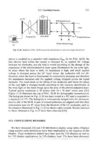
Imaging lens PAL-SLM Crossed Polarizers
Output coherent image
Fig. 11.36. Reflective PAL SLM system for incoherent to coherent image conversion.
mirror is modeled as a capacitor with impedance Z DM. In the PAL- SLM, the
bias electric field within the system is obtained by an applied AC voltage
between the electrodes, and the field is varied according to the change of the
impedance of the photoconductive layer upon illumination by the write light.
In areas where the layer is dark, its impedance is high, and small applied
voltage is dropped across the LC layer; hence, the molecules will not tilt.
However, when the layer is illuminated, its conductivity increases and therefore
the impedance decreases and the applied voltage dropped across the liquid
increases. The result leads to the tilting of the molecules and hence the phase
of the read light is changed locally according to the intensity distribution of
the write light or the input image upon the area of the photoconductive layer.
2
Typical spatial resolution is 50 Ip/mm with 18 x 18 mm active area [41].
Figure 11.36 illustrates the use of PAL-SLM for holographic reconstruction.
The hologram shown in Fig. 11.26 has been stored in a PC and is ouputted to
a standard LC-TV. The hologram is subsequently imaged onto the photocon-
ductive side of the SLM. A pair of crossed polarizers are aligned such that their
polarization axes are 45° away from the directors of the LC molecules, such as
the situation illustrated in Fig. 11.22 for electro-optic crystals. Results identical
to those obtained in Fig. 11.27 have been observed [44].
11.5. CONCLUDING REMARKS
We have discussed 2-D and 3-D information display using optics. Displays
using acousto-optic modulators have been emphasized in the majority of this
chapter. These modulators indeed have been used for 2-D displays as well as
for 3-D display applications. In 2-D displays, laser TVs have been discussed.