Page 712 - Introduction to Information Optics
P. 712
696                     12, Networking with Optics

       12.3. DESIGN OF OPTICAL NETWORK TRANSPORT


          In the previous section we discussed some critical optical network elements
       such as optical fibers, optical amplifiers, transmitters, and receivers. Now we
       consider the design of simple optical network transport when these key
       components are put together. We first will discuss the impacts of fiber
       dispersion, fiber nonlinearity, and signal-to-noise ratio (SNR); then we will
       present design examples considering all effects.


        12.3.1. OPTICAL FIBER DISPERSION LIMIT

          The electric field of a linearly polarized optical signal or pulse can be
       expressed as

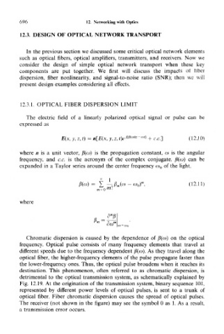
                                              mm]z  <at]
                      E(x, y, z,t)= n[E(x, y, z, t)e   ~  + c.c.]   (12. 1 0)

       where n is a unit vector, /?(«) is the propagation constant, co is the angular
       frequency, and c.c. is the acronym of the complex conjugate. fi((ai) can be
       expanded in a Taylor series around the center frequency co 0 of the light,


                                   iti — " 0

       where


                                       A,
                                           <a = coo
          Chromatic dispersion is caused by the dependence of p(w) on the optical
       frequency. Optical pulse consists of many frequency elements that travel at
       different speeds due to the frequency dependent fi(co). As they travel along the
       optical fiber, the higher-frequency elements of the pulse propagate faster than
       the lower-frequency ones. Thus, the optical pulse broadens when it reaches its
       destination. This phenomenon, often referred to as chromatic dispersion, is
       detrimental to the optical transmission system, as schematically explained by
       Fig. 12.19. At the origination of the transmission system, binary sequence 101,
       represented by different power levels of optical pulses, is sent to a trunk of
       optical fiber. Fiber chromatic dispersion causes the spread of optical pulses.
       The receiver (not shown in the figure) may see the symbol 0 as 1. As a result,
       a transmission error occurs.

