
Page 717 - Introduction to Information Optics
P. 717
12.3. Design of Optical Network Transport 70!
12.3.3. SYSTEM DESIGN EXAMPLES
The design of a practical optical transport system is complicated. Many
factors must be considered, such as the detailed channel (wavelength) plan for
DWDM systems, appropriate transmitter and receiver pairs, optical fiber
types, optical amplifiers, dispersion compensation modules, multiplexers/de-
multiplexers, and many others. This section briefly discusses system design
guidelines. We start from the design of a linear system, considering only the
so-called power budget. Then we include the fiber dispersion limit, fiber
nonlinearity limit, and noise into system design consideration based on the
optical signal-to-noise ratio (OSNR).
12.3.3.1. Power Budget
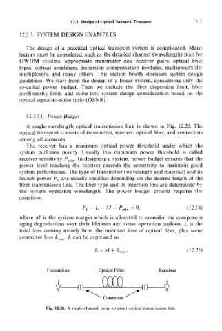
A single-wavelength optical transmission link is shown in Fig. 12.20. The
optical transport consists of transmitter, receiver, optical fiber, and connectors
among all elements.
The receiver has a minimum optical power threshold under which the
system performs poorly. Usually this minimum power threshold is called
receiver sensitivity jP min. In designing a system, power budget ensures that the
power level reaching the receiver exceeds the sensitivity to maintain good
system performance. The type of transmitter (wavelength and material) and its
launch power P L are usually specified depending on the desired length of the
fiber transmission link. The fiber type and its insertion loss are determined by
the system operation wavelength. The power budget criteria requires the
condition
P,.-L-M-P mi n = 0, (12.24)
where M is the system margin which is allocated to consider the component
aging degradations over their lifetimes and some operation cushion. L is the
total loss coming mainly from the insertion loss of optical fiber, plus some
connector loss L con. L can be expressed as
L = a/+L con , (12.25)
Transmitter Optical Fiber Receiver
Connector
Fig. 12.20. A single-channel, point-to-point optical transmission link.