
Page 718 - Introduction to Information Optics
P. 718
702 12. Networking with Optics
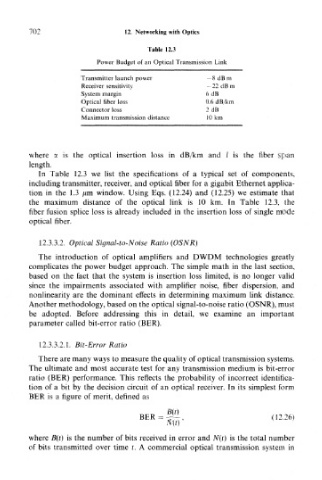
Table 12.3
Power Budget of an Optical Transmission Link
Transmitter launch power —8 dB m
Receiver sensitivity — 22dBm
System margin 6 dB
Optical fiber loss 0.6 dB/km
Connector loss 2 dB
Maximum transmission distance 10 km
where a is the optical insertion loss in dB/km and / is the fiber span
length.
In Table 12.3 we list the specifications of a typical set of components,
including transmitter, receiver, and optical fiber for a gigabit Ethernet applica-
tion in the 1.3 /mi window. Using Eqs. (12.24) and (12.25) we estimate that
the maximum distance of the optical link is 10 km. In Table 12.3, the
fiber fusion splice loss is already included in the insertion loss of single mode
optical fiber.
12.3.3.2. Optical Signal-to-Noise Ratio (OSNR)
The introduction of optical amplifiers and DWDM technologies greatly
complicates the power budget approach. The simple math in the last section,
based on the fact that the system is insertion loss limited, is no longer valid
since the impairments associated with amplifier noise, fiber dispersion, and
nonlinearity are the dominant effects in determining maximum link distance.
Another methodology, based on the optical signal-to-noise ratio (OSNR), must
be adopted. Before addressing this in detail, we examine an important
parameter called bit-error ratio (BER).
12.3.3.2.1. Bit-Error Ratio
There are many ways to measure the quality of optical transmission systems.
The ultimate and most accurate test for any transmission medium is bit-error
ratio (BER) performance. This reflects the probability of incorrect identifica-
tion of a bit by the decision circuit of an optical receiver. In its simplest form
BER is a figure of merit, defined as
(12.26)
where B(t) is the number of bits received in error and N(t) is the total number
of bits transmitted over time t. A commercial optical transmission system in